
Content
- 1 What Is a Wheel Bearing Hub Assembly and What Does It Do?
- 2 How Wheel Bearing Hub Assemblies Support Vehicle Dynamics
- 3 Warning Signs That a Wheel Bearing Hub Assembly Is Failing
- 4 Wheel Bearing Hub Assembly Generations Compared
- 5 Step-by-Step Overview of Wheel Bearing Hub Assembly Replacement
- 6 Factors That Accelerate Wheel Bearing Hub Assembly Wear
- 7 Choosing a Quality Replacement Wheel Bearing Hub Assembly
What Is a Wheel Bearing Hub Assembly and What Does It Do?
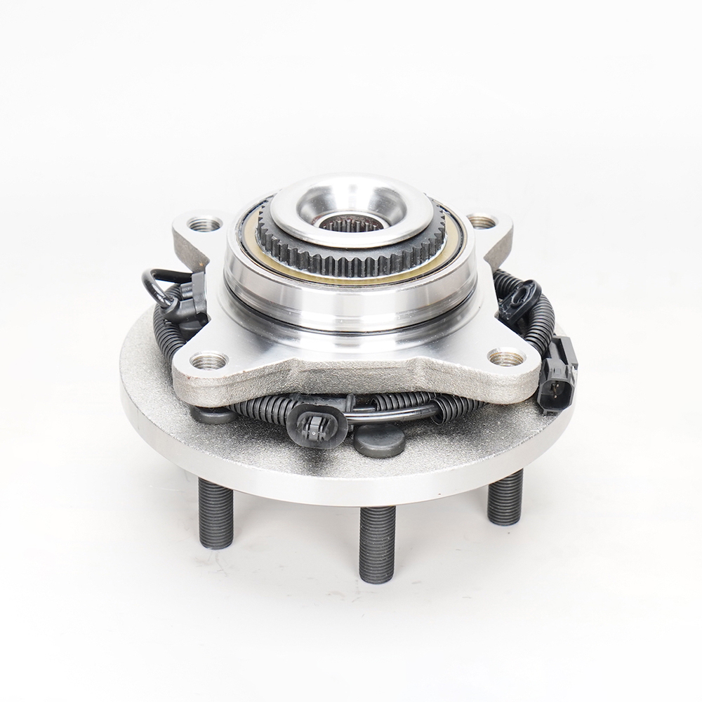
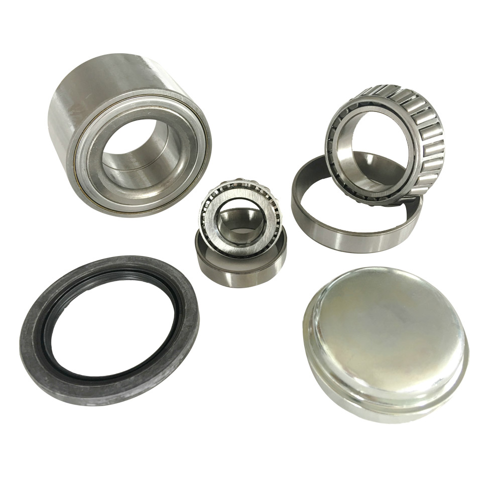
A wheel bearing hub assembly unit is a pre-engineered, fully integrated component that combines the wheel hub, bearing rings, rolling elements, seals, and in most modern designs an ABS sensor ring into a single sealed, self-contained unit. It serves as the direct interface between the rotating wheel and the stationary suspension components of the vehicle — specifically the steering knuckle or axle flange — allowing the wheel to spin freely with minimal friction while supporting the full weight of the vehicle and absorbing the lateral and axial forces generated during cornering, braking, and acceleration. The integration of all these functions into one bolt-on assembly is the defining characteristic of the modern hub unit, replacing the older serviceable design where loose bearings, inner and outer races, seals, and hub components had to be assembled, adjusted, and packed with grease individually during installation or service.
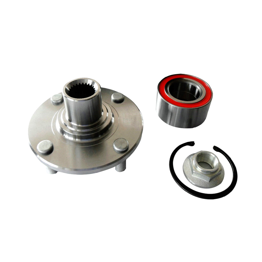
Modern wheel bearing hub assemblies are classified into three generations that reflect the historical evolution of the component. Generation 1 (Gen1) units consist of a double-row angular contact ball bearing pressed into the hub or steering knuckle, requiring a press and specialized tooling for installation. Generation 2 (Gen2) units integrate the flange for wheel or knuckle mounting into the outer ring of the bearing, simplifying installation to a bolt-on procedure while still requiring a press to seat the inner ring onto the axle spindle. Generation 3 (Gen3) units — by far the most common design in passenger vehicles produced since the mid-1990s — integrate both the wheel mounting flange and the knuckle mounting flange into the assembly, making it a completely self-contained unit that installs with standard bolts and requires no press work or pre-load adjustment. Many Gen3 units also incorporate the ABS wheel speed sensor target ring — a magnetic encoder ring — directly into the inner seal, enabling the ABS system's wheel speed sensor to read vehicle speed from the hub assembly itself.
How Wheel Bearing Hub Assemblies Support Vehicle Dynamics
The forces acting on a wheel bearing hub assembly during normal vehicle operation are complex and multidirectional. Understanding these load types explains why hub units are engineered with such precision and why even partial bearing failure has immediate consequences for vehicle safety and handling.
Radial loads — forces acting perpendicular to the wheel's rotational axis — are the primary static load, generated by the weight of the vehicle pressing down through the suspension onto the hub. On a 1,500 kg passenger car, each front hub carries approximately 375 kg of vertical load at rest, with dynamic load spikes of two to three times that value occurring during hard braking and pothole impacts. Axial loads — forces acting along the rotational axis of the wheel — are generated during cornering as lateral acceleration pushes the vehicle's mass toward the outside of the turn, loading the outer front hub in the axial direction. A wheel bearing hub assembly must accommodate both load types simultaneously throughout its design life, which typically targets 150,000 km or more in most passenger vehicle applications. The double-row angular contact ball bearing or double-row tapered roller bearing configuration used in virtually all modern hub units achieves this by arranging two rows of rolling elements at opposing contact angles, allowing each row to manage axial load from one direction while jointly handling radial load.

Warning Signs That a Wheel Bearing Hub Assembly Is Failing
Wheel bearing failure rarely happens without warning. Recognizing the symptoms early allows the hub unit to be replaced before a deteriorating bearing progresses to catastrophic failure — which at highway speeds can result in loss of vehicle control, wheel separation, or severe damage to the brake rotor, ABS sensor, and knuckle. The following symptoms are the most reliably indicative of hub bearing deterioration and should prompt immediate professional inspection.
- Humming or Grinding Noise at Speed: A low-frequency humming or rumbling noise that increases in pitch with vehicle speed and is often directional — louder on left turns when the right bearing is failing, and vice versa — is the classic symptom of wheel bearing wear. The noise results from surface fatigue on the bearing raceways and rolling elements creating uneven contact as they rotate. Unlike tire noise, bearing noise typically changes character when steering input shifts weight onto or off the suspect hub, and it persists regardless of road surface texture.
- Clicking or Snapping on Turns: A clicking noise specifically during low-speed turns — such as in parking lots or at intersections — may indicate a worn outer CV joint in drive axle vehicles, but when it occurs at higher cornering speeds and is accompanied by vibration, it more often indicates a hub bearing with advanced radial play that allows the bearing to load and unload abruptly under lateral force.
- Steering Wheel Vibration: Vibration felt through the steering wheel — particularly at specific vehicle speeds and not attributable to wheel balance or tire condition — can originate from a failing front hub bearing that introduces runout variation into the rotating assembly. This vibration is often confused with wheel balance issues, but unlike balance-related vibration it typically does not respond to wheel balancing service.
- ABS or Traction Control Warning Lights: In vehicles with integrated ABS encoder rings in the hub seal, bearing wear that allows the encoder ring to shift position relative to the sensor, or bearing contamination that corrupts the magnetic encoder signal, will trigger ABS and stability control fault codes. An ABS warning light combined with any of the mechanical symptoms above is a strong indicator that the hub unit requires replacement rather than ABS sensor service alone.
- Excessive Wheel Play: Grasping a road wheel at 12 o'clock and 6 o'clock and rocking it while the vehicle is safely raised on a lift reveals axial play in the hub bearing. Any perceptible looseness beyond approximately 0.05 mm — which is the typical maximum allowable axial play specification for a passenger vehicle hub unit — indicates bearing wear that warrants immediate replacement. Note that play measured at 9 o'clock and 3 o'clock indicates CV joint or steering component wear rather than bearing failure.
Wheel Bearing Hub Assembly Generations Compared
The three generations of wheel bearing hub assemblies differ significantly in design complexity, installation requirements, and integrated functionality. The table below summarizes the key differences to help technicians and vehicle owners understand which type their vehicle uses and what the replacement process involves.
| Feature | Gen 1 | Gen 2 | Gen 3 |
| Integrated Flange | None | One side only | Both flanges integrated |
| ABS Encoder Ring | Usually separate | Sometimes integrated | Typically integrated in seal |
| Installation Method | Press fit — requires hydraulic press | Partial press + bolt-on | Bolt-on only — no press required |
| Pre-load Adjustment | Required during assembly | Factory set | Factory set — no adjustment needed |
| Sealed for Life | No — requires regreasing | Yes | Yes |
| Typical Vehicles | Pre-1990s, heavy trucks | Some 1990s passenger cars | Most vehicles from mid-1990s onward |
Step-by-Step Overview of Wheel Bearing Hub Assembly Replacement
Replacing a Generation 3 wheel bearing hub assembly on a typical front-wheel-drive passenger vehicle is a straightforward procedure for a competent DIY mechanic with access to basic hand tools and a torque wrench, though certain steps require care to avoid damaging the new unit or related components during installation. The following process overview applies to the most common front hub replacement scenario.
Preparation and Disassembly
Begin by loosening the center axle nut — typically a 30 to 36 mm hex nut torqued to 180 to 280 Nm depending on vehicle — while the wheel is still on the ground and the vehicle's weight prevents the hub from rotating. Raise and safely support the vehicle, remove the wheel, and then remove the brake caliper and rotor or drum to access the hub. Disconnect the ABS sensor wiring harness from its retaining clips and, if accessible, unplug the connector before removing the hub assembly. On most Gen3 applications, four bolts accessed from the rear of the steering knuckle secure the hub unit to the knuckle face. These bolts are often heavily corroded in older vehicles and may require penetrating oil treatment and an impact wrench to remove without damaging the knuckle threads.
Separating the Hub From the Axle
With the retaining bolts removed, the hub assembly must be separated from the CV axle shaft that passes through its center bore. In many cases the hub will slide free of the axle after the center nut is fully removed, but in vehicles with significant corrosion between the hub bore and axle splines a hub puller or gentle persuasion with a brass punch may be required. Never strike the threaded end of the axle shaft directly with a steel hammer as this damages the CV joint and thread. Once the hub is free, the mating surfaces on the steering knuckle should be cleaned of rust and debris with a wire brush and flat file before the new hub is offered up — any raised corrosion deposits on the knuckle face will prevent the new hub from seating fully, introducing runout that causes brake rotor lateral runout and pedal pulsation after installation.
Installing the New Hub Assembly
Slide the new hub unit onto the axle shaft, engaging the internal splines of the hub bore with the axle splines. Thread the new center axle nut onto the axle — always use a new nut rather than reusing the old one, as most manufacturers use a prevailing-torque or single-use staking design that loses its locking function after the first installation. Hand-tighten the hub retaining bolts into the knuckle, then torque them in a cross pattern to the vehicle-specific specification — typically 70 to 100 Nm for M12 bolts. Reinstall the brake components, reconnect the ABS sensor connector, refit the wheel, lower the vehicle, and torque the center axle nut to specification with the vehicle's weight on the wheel to prevent hub rotation. On vehicles that stake or crimp the axle nut after torquing, this step must be performed with a suitable staking punch to prevent nut loosening in service.
Factors That Accelerate Wheel Bearing Hub Assembly Wear
While wheel bearing hub assemblies are designed for long service life, several operating and environmental factors can reduce actual service life significantly below the design target. Understanding these factors allows vehicle owners to take protective measures and set realistic replacement interval expectations for their specific usage pattern.
- Impact Loads from Potholes and Curbs: A single high-energy impact — driving at speed through a deep pothole or striking a curb — can introduce brinelling damage to bearing raceways that permanently compromises the bearing surface and accelerates fatigue wear. Vehicles regularly driven on poor road surfaces typically experience bearing failure at significantly lower mileage than highway-driven vehicles.
- Wheel Offset and Oversized Tires: Installing wheels with greater offset or larger diameter tires than specified by the vehicle manufacturer increases the effective moment arm of radial and lateral loads on the hub bearing, raising stress levels beyond the bearing's design assumptions and shortening fatigue life. This is a significant concern with aftermarket wheel fitments that prioritize appearance over engineering compatibility.
- Water and Contamination Ingress: Hub bearing seals are designed to exclude water and dirt under normal splash exposure, but extended high-pressure water exposure — such as vehicle wading, aggressive pressure washing aimed directly at the hub, or sustained driving through deep standing water — can overcome seal lip pressure and allow water infiltration. Water in the bearing accelerates corrosion of the raceways and balls, dramatically shortening service life.
- Incorrect Axle Nut Torque: Over-torquing the center axle nut preloads the hub bearing beyond its design clearance, generating excess heat and accelerating rolling element fatigue. Under-torquing allows axial movement of the hub on the axle splines that progressively damages both the hub bore and the axle shaft. Always use a calibrated torque wrench to the vehicle-specific specification — never tighten by feel or impact gun impulse alone.
- Extended Operation With a Worn Tire: Severely worn or improperly inflated tires transmit higher shock loads into the hub assembly because the tire's pneumatic cushioning is reduced. Driving on flat or near-flat tires even briefly subjects the hub to impact loads that can cause irreversible raceway damage within a very short distance.
Choosing a Quality Replacement Wheel Bearing Hub Assembly
The aftermarket wheel bearing hub assembly market spans an enormous quality range — from OEM-equivalent units produced by bearing specialists supplying original equipment to vehicle manufacturers, to low-cost imports with inadequate material specifications, inconsistent geometry, and substandard seals. The performance consequences of choosing a substandard hub unit are significant: inferior units frequently fail within 20,000 to 40,000 km, introduce ABS sensor errors from poorly manufactured encoder rings, and may have dimensional inaccuracies that cause brake rotor runout even when correctly installed. The following criteria should guide replacement unit selection.
- Reputable Bearing Brand: Wheel bearing hub assemblies from established bearing manufacturers — including SKF, FAG (Schaeffler), NSK, NTN, Timken, and JTEKT — are produced to the same material and dimensional standards as the OEM parts these companies supply directly to vehicle manufacturers. These units represent the safest choice for longevity and ABS system compatibility.
- Correct ABS Encoder Specification: Confirm whether the vehicle uses an active (magnetic encoder ring) or passive (tone ring) ABS system, and verify that the replacement hub's encoder ring matches the original specification. Installing a hub with an incompatible encoder ring will trigger ABS fault codes even when the hub is otherwise correctly installed.
- Verify Flange Runout Specification: Premium replacement hub units specify maximum flange runout — the deviation from perfect flatness of the wheel mounting surface — of 0.025 mm or less. This specification is critical for achieving low brake rotor lateral runout after installation, which directly determines whether the brake pedal pulsates during stopping. Avoid units that do not publish flange runout specifications, as this omission typically indicates the parameter is not controlled in production.
- Include a New Axle Nut: Many quality hub unit packages include a new axle nut as part of the kit. If not included, purchase the vehicle-specific axle nut separately rather than reusing the original — the locking feature on prevailing-torque nuts is compromised after the first removal, and reuse risks nut loosening in service with potentially catastrophic consequences.
The wheel bearing hub assembly unit is a safety-critical component whose condition directly determines vehicle stability, braking performance, and ABS system reliability. Recognizing failure symptoms early, replacing the unit with a quality part from a reputable manufacturer, and following correct installation torque specifications are the three practices that most reliably protect vehicle safety and maximize service interval between hub replacements across the full life of the vehicle.
